Precipitation
Basis and consequences of precipitation
measurements are worldwide most different.
We offers a complete program for the realization of
all possible tasks in the field of measurement, regulation and controlling.
Complete systems are used as well as single components.
For example:
Besides the large range of applications there is
one principle valid for all our instruments: to be compatible during the
different steps of measurement, display and output. It is also possible to adapt
smoothly all components within existing systems by using standardized outputs.
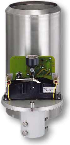
Precipitation Transmitter
General Information
This instrument is designed to measure precipitation striking the surface of the earth. The precipitation strikes a collector with a surface area of 200 cm² and then travels via a run-in sieve into a tipping scale. When a certain amount of water has gathered, the scale tips and empties, while the other half of the scale is ready to receive water again. This tipping procedure is detected by a reed switch and is made available as a pulse for an electrical Signal.
The signal is prepared and emitted on the
digital output (optocoupler) as a pulse. Simultaneously the input signal is
converted in an analog value change and made available on the analog output as a
current or voltage value. (See Models Available) The amount of the analog value
change depends on the measuring range selected. There are different measuring
ranges available (see Selection of Measuring Range). Selection is made by means
of a DIP switch and thus can be adjusted by the user to the local conditions.
The analog output is set automatically to the initial value (for example 0V...,
4mA..., 0mA...) when the measuring range transmission value has been reached.
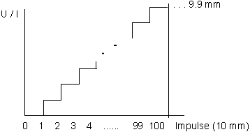
Resetting the analog output to the initial value can also be done with a RESET-impulse on the reset-input (at any time). The Precipitation Transmitter is equipped with an electronically regulated heater for winter operation.
Models Available
| 5.4033.30.040 | 0 ... 20 mA (max. 500 O ) | ||
| 5.4033.30.041 | 4 ... 20 mA (max. 500 O ) | ||
| 5.4033.30.061 | 0 ... 10V | ||
| 5.4033.31.040 | 0 ... 20 mA (max. 500/300 W) | ||
| 5.4033.31.041 | 4 ... 20 mA (max. 500/300 W) | ||
| 5.4033.31.061 | 0 ... 10 V |
The factory setting for the measuring range is 0
... 10 mm.
Technical Data
| Heating | ||
| Switch-on temperature | ||
| Hysterese | ||
| Heating power | ||
| Ambient temperature | ||
| Measuring system | Tipping bucket | |
| Resolution | 0.1 mm | |
| max. Intensity | 7 mm/Minutes | |
| analog Measuring range | adjustable ( DIP Switch) | |
| Measuring range 1 | 0 ... 10 mm Precipitation | |
| Measuring range 2 | 0 ... 25 mm Precipitation | |
| Resolution | 0.1 mm | |
| Measuring range 3 | 0 ... 20 mm Precipitation | |
| Measuring range 4 | 0 ... 50 mm Precipitation | |
| Resolution | 0.2 mm | |
| analog registration | with automatic overflow | |
| with external reset | ||
| Reset input | Optocoupler | |
| Input voltage | 5 ... 30 V | |
| Pulse | ³ 20 msec | |
| Measured value output | ||
| 1. Digital | ||
| Optocoupler | 1 Pulse/Tipping bucket | |
| Pulse length | >= 100 msec | |
| U (max.) | 30 V | |
| 2. Analog | ||
| Voltage output | 0 ... 10 V (corresponds to...s. Measuring range) | |
| Current output | 0 ... 20 mA (corresponds to s. Measuring range) | |
| 4 ... 20 mA | ||
| Non linearity | ± 0,2 % (-30°C ... 60°C) | |
| Offset error | < 0,3 % (-30°C ... 60°C) | |
| load | 500 W Power supply 24 V AC/DC | |
| 300 W Power supply 10 ... 14 V DC | ||
| Power supply | 1. 24 V AC/DC (±15%) | |
| 2. 10 ... 18 V DC | ||
| Power consumption | approx. 20 mA (without heating) | |
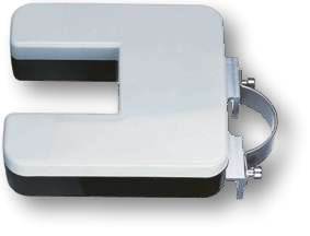
Precipitation Monitor
Range of application
The precipitation monitor transmits signals to determine the beginning and the end of precipitation and the duration of the period of precipitation as required by meteorological services.
In addition, the precipitation monitor can be used to report status or to transmit control signals to connected rain protection devices such as windows, air vents or awnings.
Mode of operation
Drops of precipitation are detected by means of a IR light barrier system. The drops interrupt the light barrier, thus triggering a signal in the connected electronics.
The instrument is equipped with an "event filter" to prevent misinterpretation of data due to the effects of insects, bird droppings, falling leaves etc. Precipitation is only reported if at least 2 drops pass through the light barrier system at a certain speed within 50 seconds of each other. Precipitation is reported by a cut through relay. An adjustable switch-off delay smoothes the switching signals when there are a number of short-term precipitation events.
The instrument is equipped with a heating system for extreme weather condition. This maintains a temperature of > 0°C on the surface of the monitor (housing cover) in order to prevent ice from forming and snow from piling up. A soiling of the sensor windows is avoided to the greatest possible extend by their vertical position that keeps the windows moisture free. Therefore, the maintenance requirements are very small.
By using PTC`s as heating elements the power input can reach a high peak value during the switch-on phase. This value must be limited on max. 50 W (for ex. by means of the Thies Power Supply Unit 5.4102.50.002).
Technical data
DATALOGGER DL 15
The DL15 Weather
Station Data-Logger forms the centre - unit of a system providing the basic
needs of a data capture unit through to a fully automated solar - powered
weather station. The unit will accept and store data from a wide range of
meteorological and environmental sensors, storing the data in a 256 k byte
randomaccess memory. Downloading of the data is achieved through either a
standard 256k byte 'smartcard' or an RS 232/422 lap-top computer connection or
in an online mode using a telephone modem and a PC. Alternatively, the data
can be transmitted immediately when it is required, in situations such as
airtraffic control
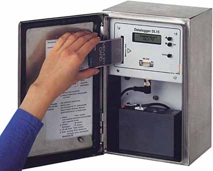
Provided with a 2-line, 16-characters LCD display the basic unit will accept 5 digital and 10 analogue inputs, each provided with its own input-matching card. However; by using an expansion board, the number and types of input can be varied to suit the application. Normally, the 'zeros' and relative settings of the sensors in use for each input-card are 'factory-set'.
The DL15 is supplied complete with menu-driven software in EPROM which also permits connection with the unit using only a basic terminal without the need for additional software.
Additional optional features include alarm functions and relay outputs, to activate visual and audible alarms at excessive measured levels, or to activate associated equipment. A further advanced option includes synthesised speech output-readings to a telephone system for dial-up interrogation.
The basic unit is contained for security and weather-proofing in a locked IP 65 steel housing. The unit's high-quality construction and capability in remote operation makes it particularly suitable for installation in difficult and harsh environmental operating conditions.
Data Transfer
The data can be read from the memory of the data logger by three different methods:
NOTE: The reading of the memory data requires a Readling Unit when the Smartcard is used
Sensors Digital and Analogue
A large number of meteorology, environmental research and aviation authorities already use high-precision Thies instruments for the interpretation of weather data. All of these instruments are directly compatible with the DL15 Data Logger and will together form a modern system to satisfy government legislation and the needs of commerce and industry which demands environmental and meteorological monitoring and recording.
Simple Operating and Monitoring
The data logger is 'user friendly' and is easily set up by reference to the LCD display and operation of three push- buttons which control the data transfer and the time intervals. The operation of all the internal functions are menu driven.
![]()